Guides / Reference
Differential pairs & length tuning
USB, LVDS and similar signals travel as coupled pairs. The app routes a pair as one object and shows how close the result is to the declared impedance target.
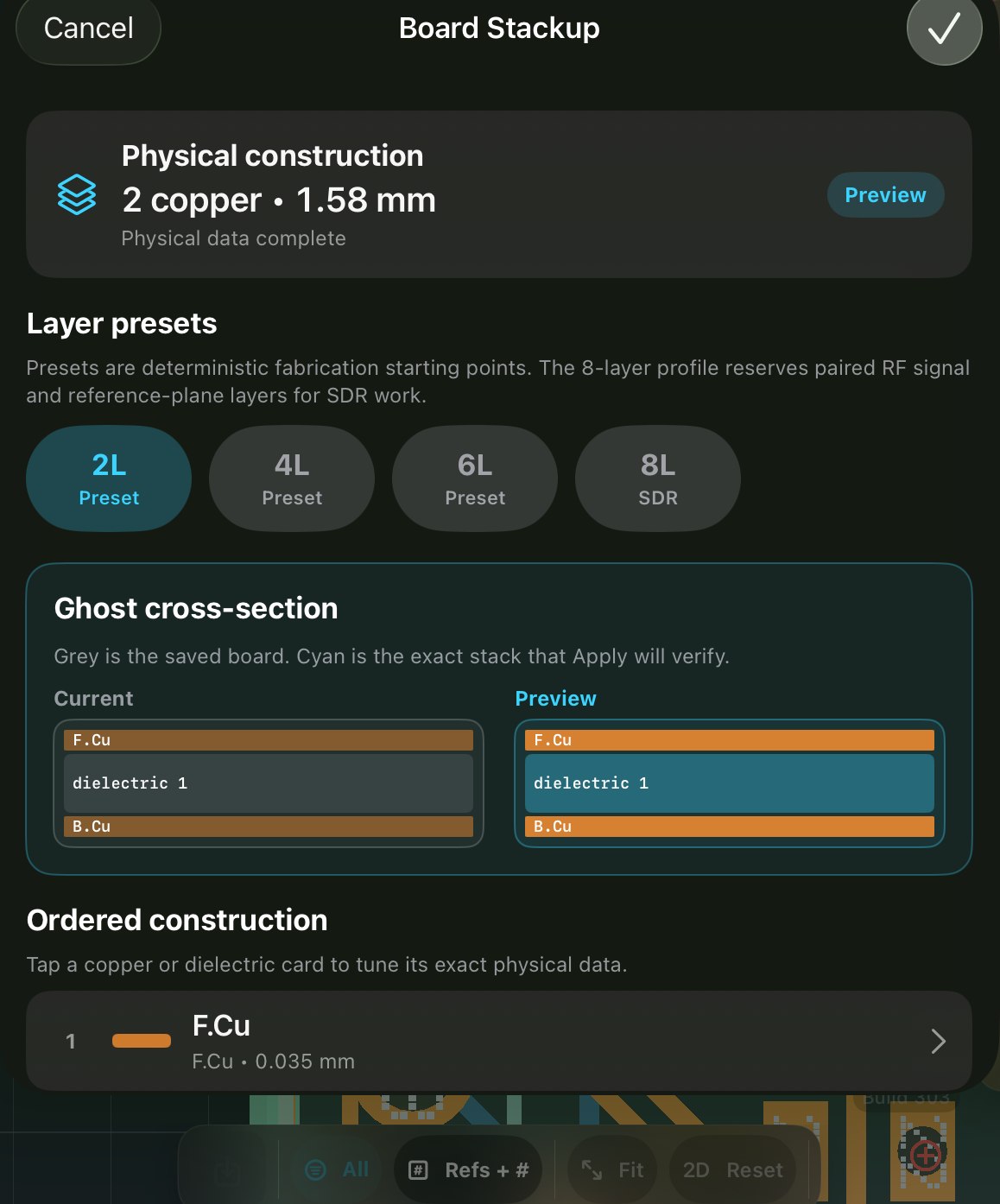
- State the intent in the stackup
Impedance targets (50 Ω single, 90/100 Ω differential) live in the stackup editor, intent declared where the geometry that realises it is decided.
- Route the pair
Pair routing engages for nets under a differential target; the routing-time readout shows achieved vs target as you go.
- Match lengths
Where skew matters, length tuning adds meanders to a trace you have drawn, to bring it inside its length tolerance, and the readout shows the difference so you don’t measure by hand. Guides that steer a net to a target length aren’t built yet (see the limits below).
When to care: below roughly 10 MHz, rarely. At USB 2.0 high speed and faster, always. Marginal boards in between may pass bench testing and still fail intermittently, which is the expensive version of this mistake.