Guides / Reference
Stackup & impedance targets
The stackup is the board’s cross-section: how many copper layers, what’s between them, and what impedances the geometry should hit.
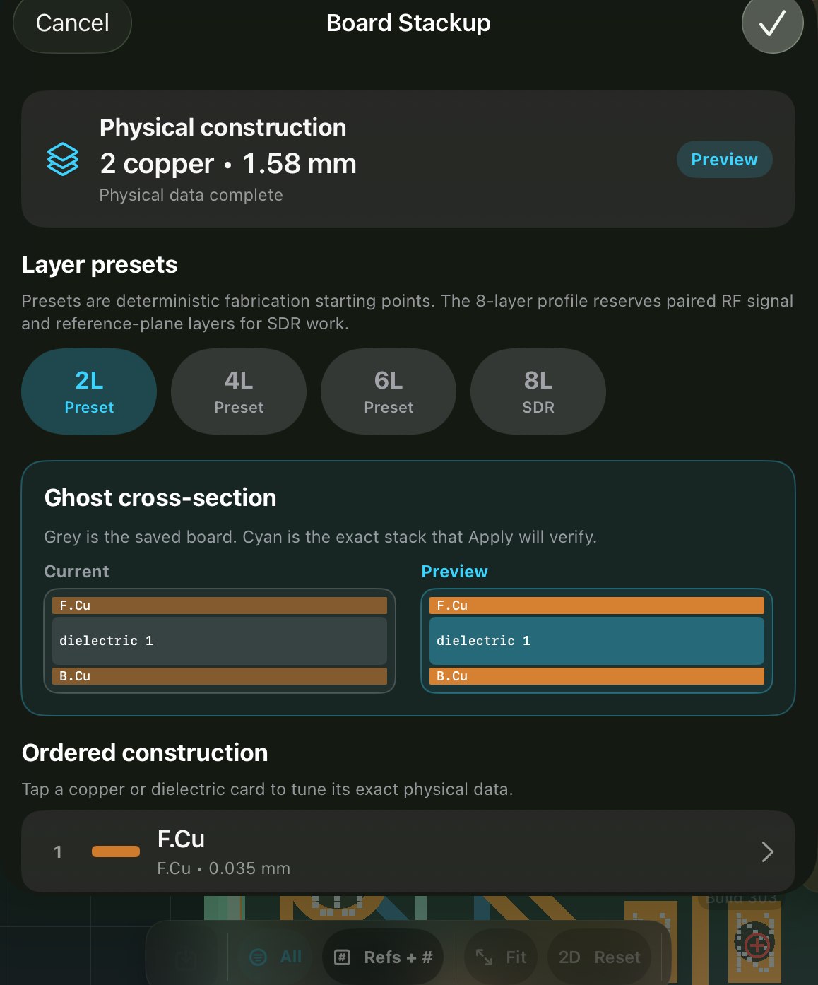
- Set the copper count
Layers ▸ the copper-count row ▸ 2, 4, 6 or 8. Inner layers appear in the list as they’re created.
- Declare targets
In the stackup editor, set 50 Ω single-ended and 90/100 Ω differential targets. Nets under a differential target get pair routing; the route-time readout reports against the target you declared.
On desktop tools the usual workflow is an impedance calculator whose result you transcribe by hand. Declaring the target here lets the app apply it to every trace that needs it.