Build a Heltec LoRa clone
An ESP32-S3 + SX1262 LoRa board with USB-C, a Li-ion charger and an OLED header, in the spirit of the Heltec WiFi LoRa 32 V3. Blank board to fab files, on iPad.
What you’re building
You pick five chips. PCB Canvas adds each chip’s support parts, sourced from datasheets and real boards, wires power by net name, and the auto-router handles the remaining connections.
Parts
Search each name once in Add Part and take the top result.
| Search for | Role | What the app adds |
|---|---|---|
ESP32-S3-MINI-1 | MCU module (U1) | Decoupling, EN pull-up and RC, boot pull-up, USB-C receptacle, ESD diodes, reset and boot buttons |
SX1262IMLTRT | LoRa radio | 31 parts from Semtech's reference design: DC-DC inductor, 32 MHz TCXO, RF switch, matching network, U.FL connector |
CP2102N | USB-serial bridge | Decoupling and reset pull-up |
TP4054 | Li-ion charger | Charge LED, 2-pin JST PH battery connector, USB/battery power path |
AMS1117-3.3 | 3.3 V regulator | Input and output capacitors |
OLED header | 4-pin 2.54 mm header (J) | Nothing, you wire it by hand |
Steps
- New board
Boards ▸ New Board ▸ Create.
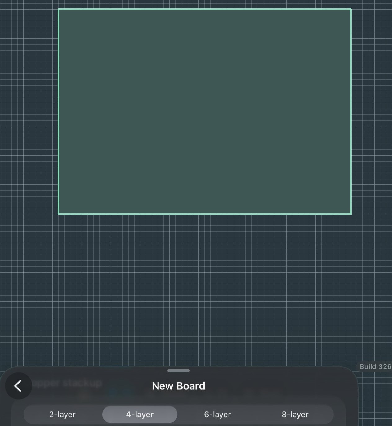
The blank 50 × 26 mm board. This run selects four layers at creation. - Use four copper layers
Open Layers in the left rail and set the copper count to 4. The two inner layers become the ground and power planes the router uses.
Why four layers: the two inner layers become uninterrupted ground and power planes, so every signal has a return path directly underneath it. That is most of what good high-frequency layout means. The outer layers stay free for parts and routing. - Add the MCU
Add Part ▸ search
ESP32-S3-MINI-1and take the top result. In the support offer, tap Place All. USB-C, ESD and the buttons start ticked; untick any you don’t want with Include in Place All.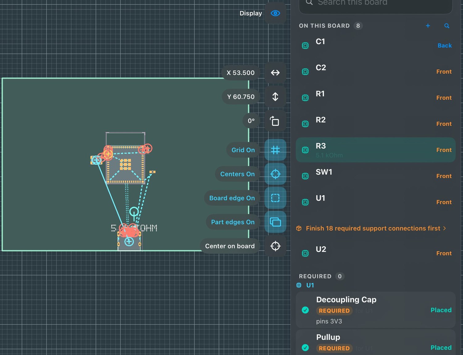
After Place All on the ESP32-S3 offer: C1, C2, R1 to R3 and SW1 placed, with the LDO suggestion below. This step took 39 seconds in the scripted run. Why a module, not a bare chip: the MINI-1 is the ESP32-S3 die plus its flash, crystal and RF matching, already laid out and FCC/CE certified under a shield can. The radio section is the hardest part of a board like this, and the module means it’s already done. - Add the radio
Add Part ▸
SX1262IMLTRT. When the offer asks which antenna, pick U.FL. Tap Place All.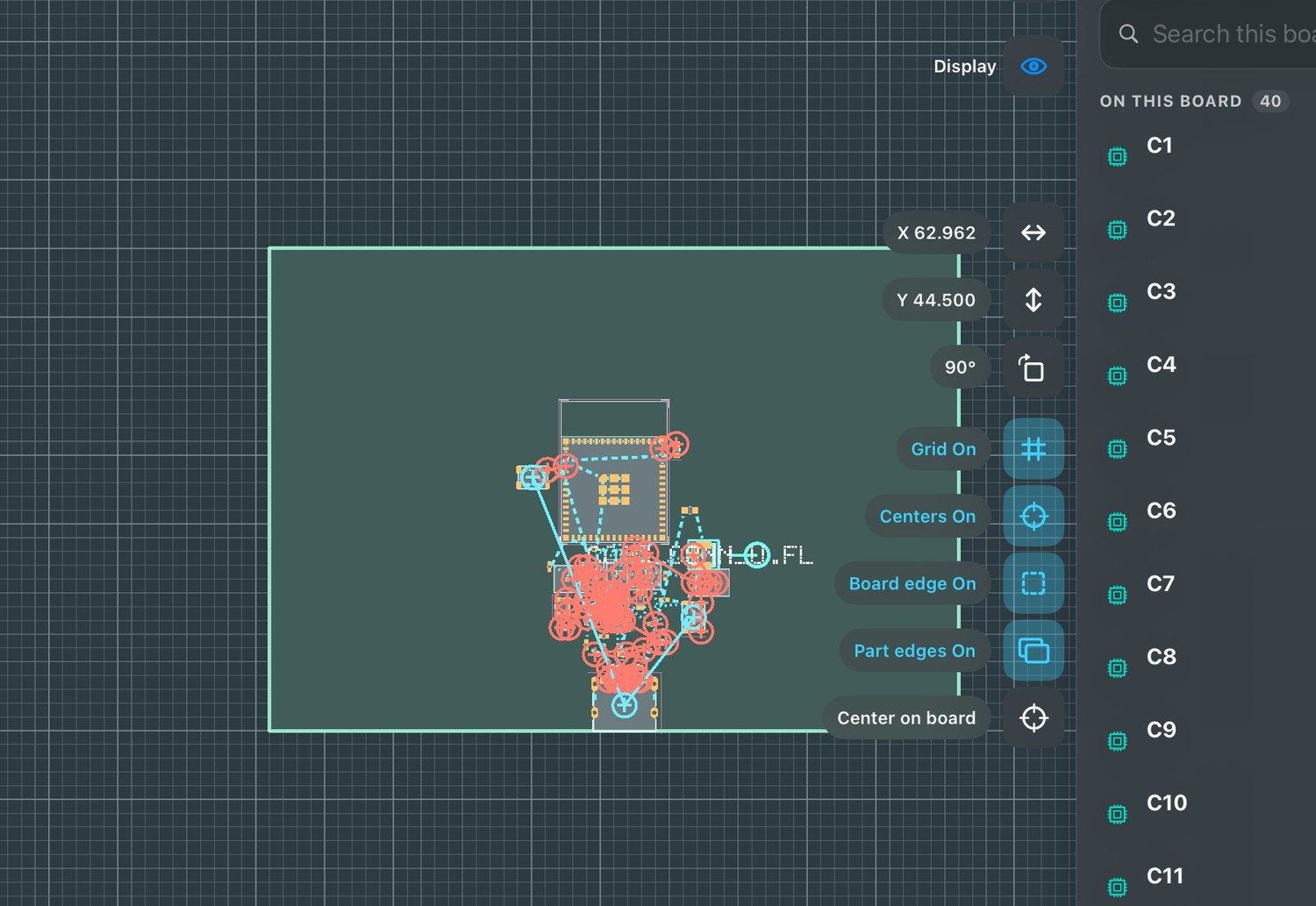
The radio’s 31 support parts: TCXO, DC-DC inductor, RF switch, matching network, and the U.FL connector chosen at the antenna prompt, placed as one offer. Why the app asks about the antenna: the right antenna depends on your enclosure, band and budget. A U.FL jack suits an external whip antenna; a chip antenna needs a ground keep-out. The choice changes the matching network and keep-outs, so the app asks instead of assuming. - Wire the radio in one tap
In the radio’s support offer, open Connect SX1262 to U1 and choose Heltec V3 pins. All seven lines join by name; one Undo removes them.
What those seven lines are: four SPI lines (the data bus), plus RESET and two radio status lines, BUSY and DIO1, that the driver polls. The pin assignment follows Heltec’s V3 schematic, which is why Meshtastic’sheltec_v3firmware target boots on this board unmodified. - Add the bridge, charger and regulator
Add Part ▸
CP2102N, thenTP4054, thenAMS1117-3.3, tapping Place All each time. - Choose battery polarity
On the charger’s battery connector, pick BAT+ on pad 2 for Adafruit and SparkFun cells, or BAT+ on pad 1 for stock KiCad JST PH. The menu shows how many real boards use each. A cell plugged into the wrong one is reversed.
Why this is a choice and not a default: JST-PH battery pigtails disagree in the wild. Adafruit and SparkFun wire BAT+ opposite to the stock KiCad footprint, and a reversed cell is destroyed on contact. The menu shows how many real boards use each convention so you can match the cell you actually own. - Let power wire itself
Regulator output, ESP32, radio and bridge join
3V3. USB feeds the charger, and USB or battery reach the regulator throughVSYS. Anything left without a supply is named in Problems. - Wire USB serial
Enter Route. Connect CP2102N TXD (pad 18) to U1 U0RXD (pad 40), and CP2102N RXD (pad 17) to U1 U0TXD (pad 39).
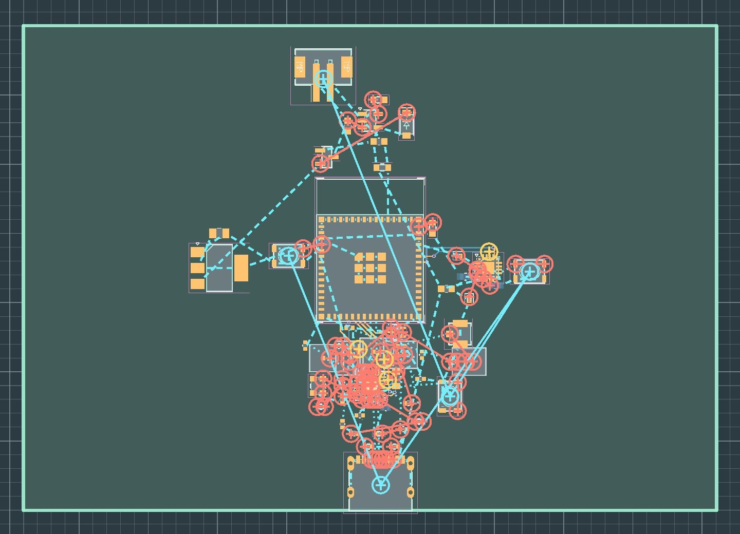
Wiring in Route mode: tap a pad, tap its partner, then Connect. The header counts the remaining connections. - Add the OLED header
Add Part ▸
OLED headergives the standard 2.54 mm 1×4. Wire GND, 3V3, SDA to U1 GPIO17 (pad 21) and SCL to U1 GPIO18 (pad 22). - Auto-route
In Route, tap Auto-route all. The line under it counts connections left. On our reference run it routed all 58 in a few seconds.
Why the radio was wired before auto-routing: power and logic only need legal, connected copper, which the router handles well. The RF path from radio to matching network to antenna, and the SPI bus, carry constraints the router can’t infer, so those were placed and connected deliberately first. - Check and export
Open Problems: anything blocking sits under “to fix” with a plain reason. Then Boards ▸ Export for Manufacturing ▸ Generate for Gerbers, and Export a KiCad copy for the .kicad_pcb.
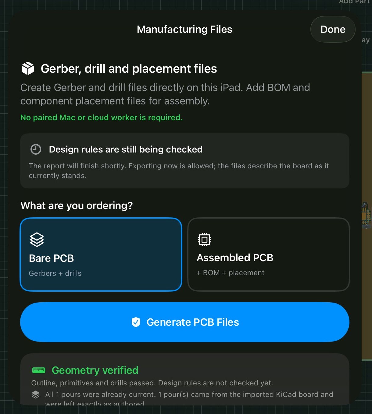
The export sheet at the end of the run: geometry verified on the iPad, no paired computer required. Measured on our reference run: the auto-router finished all 58 remaining connections in about 7 seconds, and the export produced validated Gerbers, drills, BOM and placement on the iPad. The scripted end-to-end run takes about 37 minutes; expect longer your first time through.
Wiring reference
Radio lines follow Heltec’s WiFi LoRa 32 V3.2 schematic; Meshtastic’s heltec_v3 variant agrees. ESP32 pads are for the ESP32-S3-MINI-1.
Radio (joined for you by Connect SX1262 to U1)
| Signal | SX1262 pad | ESP32 GPIO | MINI-1 pad |
|---|---|---|---|
| NSS | 19 | 8 | 12 |
| SCK | 18 | 9 | 13 |
| MOSI | 17 | 10 | 14 |
| MISO | 16 | 11 | 15 |
| RESET | 15 | 12 | 16 |
| BUSY | 14 | 13 | 17 |
| DIO1 | 13 | 14 | 18 |
USB serial and OLED (wired by hand)
| Signal | ESP32 GPIO | MINI-1 pad |
|---|---|---|
| UART RX ← CP2102N TXD (pad 18) | 44 | 40 |
| UART TX → CP2102N RXD (pad 17) | 43 | 39 |
| OLED SDA | 17 | 21 |
| OLED SCL | 18 | 22 |
Before you order
Known limits in the current build, with fixes in progress:
- Board size. Support parts currently grow the outline well past a real Heltec’s 50 × 26 mm. Compact, two-sided placement is on the way.
- Regulator on battery. The AMS1117 drops out on a single Li-ion cell, so this board runs properly from USB only. A low-dropout choice (Heltec uses the CE6260B33) is coming.
- KiCad’s own check. Opening the export in KiCad can show track-width errors, because a project rules file isn’t exported yet. Gerbers are unaffected.
- Not modelled yet. Heltec’s Vext power switch and battery-voltage divider; the OLED is a hand-wired header.
- Band. Matching values are for 868/915 MHz only.